STAR, execute an ILS approach and land on runway 06L at CYUL.
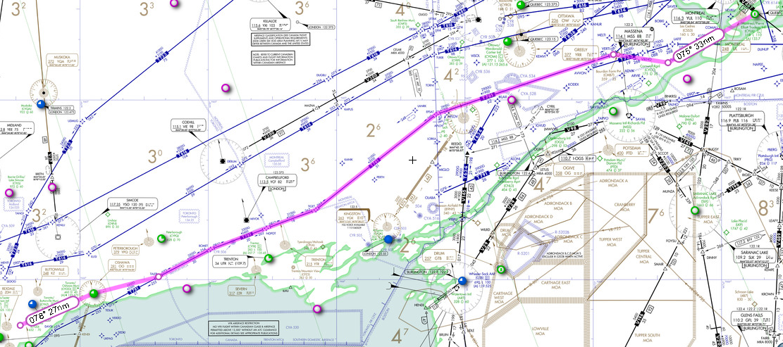
Flight route. We will be flying the following route, calculated by the freeware RouteFinder (rfinder.asalink.net):
CYZD
- dto - OO - dto - TALEB - q921
- VERTI - dto - HABBS - star - CYUL
We will take off from runway 15, there is no SID at CYZD, but
we will
use STAR at arrival. We will use HABBS3
STAR, execute an ILS approach
and land on runway 06L at CYUL.
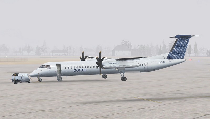
First, load the MJC8 Q400, logically Porter livery, at CYZD. Open the main entry (Shift+E) to let the passengers in. Normally, the GPU should be already connected (if it is not, you can request GPU from FMS DATA/SERVICES menu, or start the APU). You can also load a saved situation "CYZD-CYUL Sample Flight".
We will now use the included "MJC84 Control Panel" application to configure the aircraft. Please note that while doing so, the FSX should run on the background with the MJC 8Q400 aircraft on the ground. The addition of the required data for fuel, passengers and bags would be derived from the dispatch release and the station load manifest which the ramp or gate agent will give to your flight attendant. Since this is a delivery flight, we are going to have some Majestic personnel on-board to meet and greet our delivery customers in Montreal. So we will only have a few hundred pounds in the cargo bins with 30 passengers. The average fuel burn for a flight of about an hour is about 1250lbs per engine (2500lbs), and we will be filling the tanks, as we plan to have a celebratory flight for the delivery customers in Montreal.
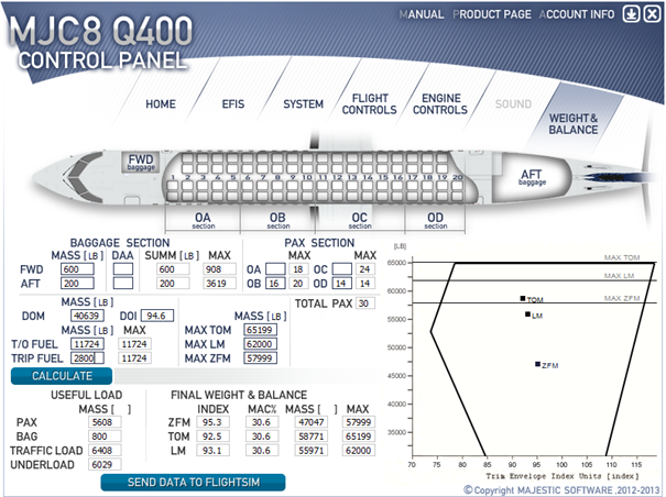
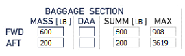
Baggage Loading
In the forward baggage compartment we have 600lbs of luggage for the
passengers, and in the rear compartment there is 200lbs of company
T-shirts, souvenirs, etc. For future use if you choose to use a baggage
count for FWD and AFT compartments, the DAA columns can be utilized,
also be aware that the FWD compartment is capable of a MAX load of 908
lbs., and the AFT compartment a MAX load of 3619 lbs.
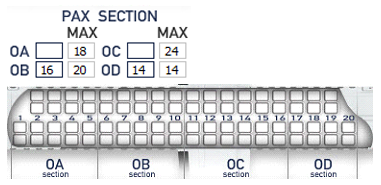
Passenger Loading
We have 30 passengers on-board with 16
seated in the OB and 14 seated in the OD sections. The Q400 passenger
loading is broken up into 4 sections for proper determination of CoG
calculations. You will also notice on the EFIS page of the Load Manager
Configuration tool that one is able to select the use of Kg or Lbs. You
will notice that each of the four boxes has a MAX passenger limit that
can be loaded into each section.
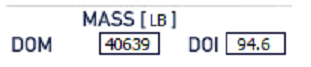
Dry Operating Mass (DOM)
The DOM (Dry operating Mass) better known as the BOW (Basic Operating
Weight) is 40, 639lbs with a DOI (Dry Operating Index, or BOI (Basic
Operating Index) if 94.6. This will be adjustable if users would like
to change it to suit a particular airlines SOP.
Fuel Loading
We have already discussed that we will be
filling the tanks for this leg (although the fuel is probably cheaper
in Montreal). The Max allowable uplift for fuel on the Q400 is 11,724
lbs., but this leg CYZD to CYUL is only going to require about 2600
lbs. of fuel for all phases of flight, but we'll add an additional 200
lbs. buffer and round it off to 2800 lbs., the weather at our origin,
en-route and at our destination is not a factor, so there will be no
need for an alternate or additional holding fuel apart for the standard
15 minutes. Also bear in mind that the tanks have been filled so we
have options if the need arises. Press the CALCULATE button to
calculate the weight and balance.

The next block of data defines what the aircraft performance
and structural weights are
- These can be changes based on specific airline aircraft weights if
one chooses to do so
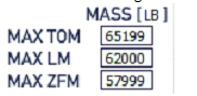
Once this is complete we now have to look at the CALCULATE button which should be selectable at this point, somewhat of a bright blue color. Upon calculating the value for bags, passengers and fuel, the load manager with now give us data pertaining to the aircraft's final weight and balance. If these values have been properly computer you should have an aircraft that is within CG limits.
Useful Load
The Useful Load Section gives a break-down of the
passenger and baggage compartments. We'll see that the MAX pax load is
5608 lbs. and the MAX baggage load is 800 lbs., which gives us a total
payload of 6408 lbs., allowing us to be able to load an additional 6029
lbs. (Under-load) if the need arises.
Final Weight and Balance
The Final Weight and Balance shows
what our ZFM/ZFW, TOM/TOW and LM/LW are with the associated index and
MAC%. Over to the right you will see the accompanying load sheet with a
graphical representation showing where the CoG is (AFT, CENTER or FWD).
From the example shown we can see that our CoG is more or less
centered. We can therefore conclude the aircraft configuration by
pressing the "SEND DATA TO FLIGHTSIM" button, closing the MJC84 Control
Panel application and switch to the FSX to begin with the the cockpit
preparation.
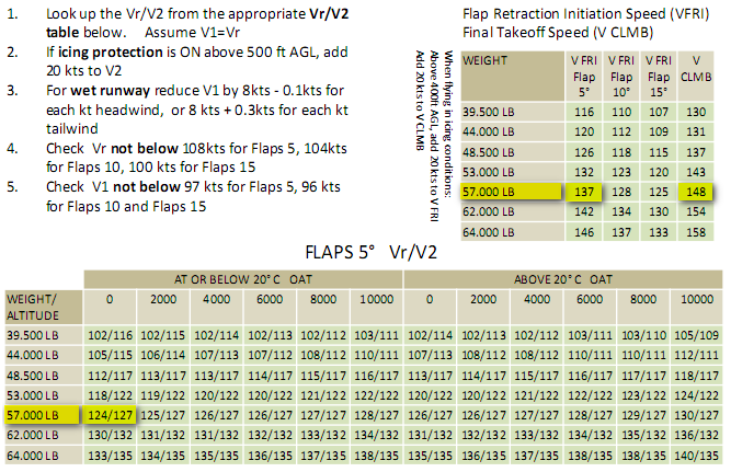
We have determined that our takeoff weight is going to be 58771 lbs., since CYZD is not a large airport it is not likely that we will be burning more than 100 lbs. of fuel for taxi, so I am going to use the takeoff weight numbers for 59000 lbs. These numbers can be accessed from the takeoff/landing data provided in the manual, or by using the AuraSim Instruments module (which is quite a handy tool for quick reference data). For this tutorial we'll use the takeoff charts provided in the manual.
You will notice that unlike some charts which incrementally increase their weights 500/1000 lbs. at a time, this one reflects a range for which the takeoff speeds are good. So for 59000 lbs. we look at the 57000 lbs. line and are able to determine that those speeds are good. The field elevation for CYZD is below 2000 feet so we choose 0 and the temperature at the field is 13 degrees Celsius. This gives us a V1/VR of 124 kts., V2 of 127 kts., VFRI of 137 kts. And VCLIMB of 148 kts.
Takeoff chart
This data now needs to entered into the PFD which is fairly simple and straight forward. Both the captain's and first officer's speed bug references which is located on the PFDs need to be updated. Under the glareshield in the left uppermost corner is the SEL button which when pressed will highlight the V1 speed bug indicator, next to the SEL button is a SEL knob used for selecting the desired speed reference.
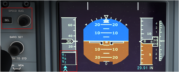
As you can see this was fairly easy, if you have incorrectly entered a value you can simply press the SEL button until you get to the desired V setting and change the value.
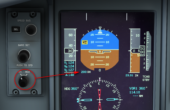
DH/MDA Setting
Next step is to set the Decision Height (DH)
or MDA (Minimum Descent Altitude). This is achievable by simply right
clicking on the DH/MDA knob (you will have to switch the knob to MDA if
this is the setting of choice) which is located below the BARO SET
knob. If not set aural altitude alerts won't be heard.
Altimeter Setting
The Altimeter setting knob is located just below the speed bug knob and
right clicking will decrease, while left clicking will increase the
value of the kohlman's window.
Switching on ARCDU will start the default announcement scenario (if the passenger door is open). You will hear some music too. Now we are ready to program the FMS.
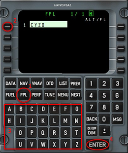 |
Switch on the FMS by pressing ON/OFF button. After a short test sequence, the FMS is ready for use. Press "Accept" to confirm the initial Position shown by the FMS. Press FPL button to start entering the flight plan. Select the first line and enter the departure airport name (CYZD). Press Enter twice to confirm the choice. You can click on the FMS screen to bring up the Popup window. |
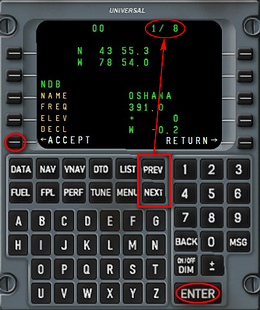 |
Select the second line to enter the second point in the
flight plan
(OO). When you confirm the entry by pressing Enter, the FMS shows a
summary page. If more than one point exists for the given name, several
pages
will be shown. You can choose the correct one by pressing PREV and NEXT
buttons. Press Enter or LSK5 to confirm. By default, the first page
shows the point closest to the last point in the flight plan. After entering the OO waypoint, enter the next TALEB waypoint in the similar way. |
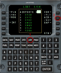 |
Next, we should take the airway Q921 up to the point VERTI. Select the forth line, then press LIST. |
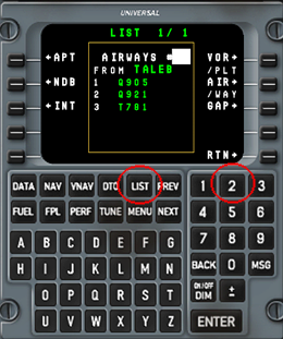 |
Press LSK7 to show the list of airways from the current point. Here, we have 3 airways, the one we need is #2. Enter 2 on the numeric pad, then press Enter. |
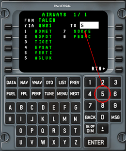 |
Now select the final point. VERTI is #5. Enter 5, then press Enter |
 |
The FMS inserts the piece of the flight plan which takes the route Q921 adding the necessary waypoints. |
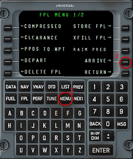 |
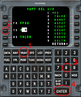
Insert the next waypoint HABBS. After that select the
next empty line in the flight plan and
enter the destination airport (CYUL). Press MENU button and then the LSK adjacent to the ARRIVE-> prompt |
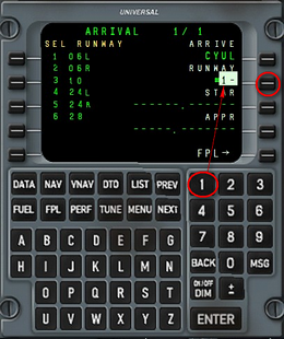 |
Press LSK9 (ARRIVE) to show the list of runways |
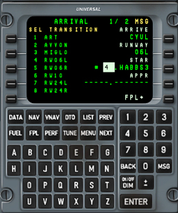 |
The runway 06L is #1 in the list, type 1 and press Enter. Select STAR HABBS3 (#2). Select transition (we take #4 for RWY 06L) |
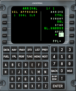 |
Select the approach by pressing LSK9 and entering its number (only one proposed here). At the end, press LSK10 to insert the selected procedures into the flight plan |
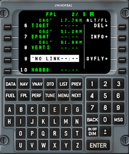 |
Now we have the entire flight plan in the FMS. There is a number of *NO LINK* lines some of them should not be deleted. To delete a line, select it, then press LSK6 (DEL) twice. There is always a *NO LINK* line between the STAR and the approach, it should typically be deleted when the approach clearance is obtained. For the purpose of our flight, we will however delete it right away. |
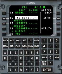 |
The *NO LINK* line after the RWY06L entry should not be deleted - the FMS deletes it automatically if missed approach is selected. You might also notice that the XULTA waypoint is listed twice, prior to, and after the *I06L* (Page FPL 3/5). This arrangement which is often referred as "sandwich" must be always present and verified. Sometimes, when using a combination of some particular STAR and Approach the sandwich will not appear, in this case the first approach waypoint must be entered manually in front of the approach. |
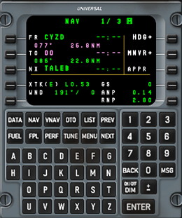 |
Press the NAV button to show the navigation page. Make sure that FROM and TO points are correctly displayed. TO should display the next waypoint. |
Close the doors (Shift+E). Overhead: switch on red
anti-collision
(right click) and position lights, turn on passenger signs, and request
pushback. To do that, press DATA button on the FMS and select SERVICES.
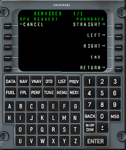
The right side buttons (LSK6 - LSK9) are dedicated to
pushback. Request
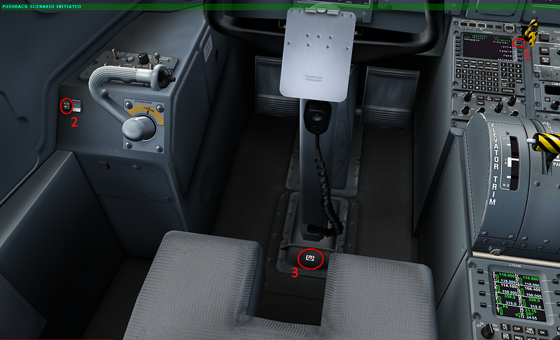
pushback by pressing LSK6 (STRAIGHT). The pushback scenario is
initiated. You will hear a dialog between the captain
and ground crew. The communication with ground crew is signalled by a
light on the captain side console (2). You will be requested to release
parking brakes, then to start the engine #2 during the
pushback. Press LSK7/LSK8 to turn left/right during the pushback. Press
LSK9 (End) to stop. You can hide the yoke by clicking on its base (3)
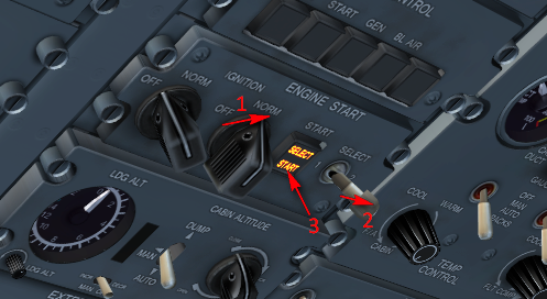
To start the engine #2, turn ignition knob (1), select the
engine #2
(2) and press the start button (3). Generally, right mouse clicks will
move switches/knobs to the right/upwards/clockwise. Left clicks will
move them to the left/downwards/counter-clockwise. If a switch has only
two positions, left and right clicks will have the same effect. To
select the engine 2, right click the switch. It will remain fixed to
the right untill the engine is started, then return to neutral
position. Push the START button to activate the starter, and move the
right Condition Lever to START&FEATHER. Then you can start the
engine #1. In heavy snow conditions, the engine intakes can get stucked
with snow and the engines won't start. Open the bypass doors (ENGINE
INTAKES, ice protection panel on the overhead) to let air get into
engines by a little inlet located under the nacelles.
The engines are started and props rotating at approx 220 rpm.
Set CL to
max. The engines will spool up to 660 rpm, which is the right rate for
taxi. The GPU will disconnect as soon as the engines reach 440 rpm.
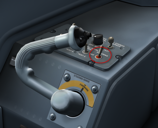
Switch on taxi lights (2), switch off external power and switch on nose
wheel steering. Switch ON the PTU and Standby Hydraulic Pump, Both fuel
pumps, Select the autofeather and select the spoilers Flight/Taxi
switch to Taxi.
Depending on the settings, the steering tiller can be controlled either
by the mouse, or by ailerons axis, or by spoiler axis (which is the
recommended setting). The steering is effective under 40kts. You can
also use rudder axis to turn the nose wheel withing 8 deg. angle.
Tiller steering alows to turn the nose wheel up to 70 deg. in each
direction. If auto differential thrust is enabled in settings, the PL
will move separately to use differential thrust and simplify turns.
Start taxiing. Release Parking Brakes and use the Power Levers
to
control taxi speed. Check that PROPELLER GROUND RANGE indicator shows 1
and 2, meaning that the power setting is inside the range for taxiing.
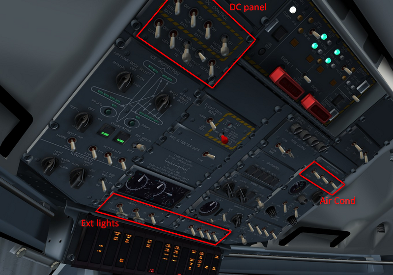
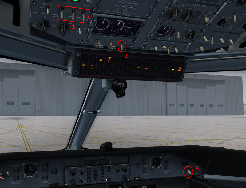
During taxi, switch on pitots heaters (1) and anti-skid system (3). Set
all 3 altimeters to 29.97 inches. Set the autopilot: Select FMS1 as the
PFD navigation source, Press TO/GA button on a side of the Power Lever,
this will make the Flight Director bars appear on the PFD, commanding
the 9 degree pitch and the level flight. Select the heading of 150
degrees, press HDG on the autopilot panel, select the altitude of 25000
feet, press ALT SEL, finally press YD to engage the Yaw Damper. The PFD
top line should now read "GA, ALT SEL and HDG SEL". Switch
on windows heaters on the overhead : WINDSHIELD sub-panel, left knob to
WARM UP, right switch to PLT SIDE WDO/HT ON. If the windows are misted,
open side window de-mist valves (little levers under the
side windows)
Check flight controls during taxi. The caution panel should be
black
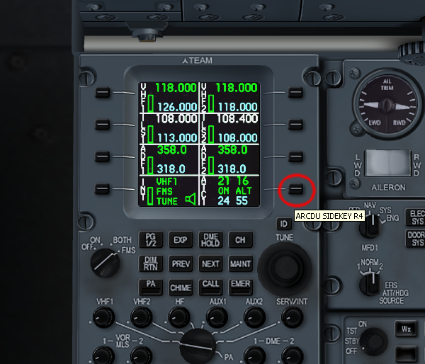
now. Set the flaps to 10 deg. Activate the Transponder and the TCAS by
pressing and holding the ARCDU LSK8 button for more than 2 seconds.
Before takeoff: Set the spoilers to "flight", switch on
landing lights,
switch off taxi lights and set anti-collision lights to white. Set
bleed flow to MIN on air condition panel. Turn OFF bleeds #1 and #2 and
select the Windshield heat switch to NORM. Switch the MFD2 to NAV mode,
and press the right WX/TERR button to activate the weather radar
overlay. Now, switch on the weather radar on the pedestal (it will warm
up during a minute, showing blue background on the MFD2)
Takeoff: Make sure the steering tiller is centered, Release
the control
lock. Set PL to RATING, the engines will spool up to 1020 rpm. Control
the aircraft with rudder during the takeoff run, don't use steering
tiller. When passing Vr, start rotating till 9 degrees pitch initially
(but no faster than 3 degrees per second), retract the gear. Maintain
the V2 speed until passing 1000ft, than switch ON the autopilot, select
IAS on the autopilot panel, using the Pitch Wheel to set the 180 kts
target speed, as indicated on the top of the PFD, press NAV to activate
the LNAV guidance. When passing 150kts retract flaps, reduce the
Condition Levers to 900, turn ON the bleeds and set the bleed flow to
the MAX position. You may also utilize the rudder trim knob (on the AFT
part of the pedestal) to align the slip/skid indicator.
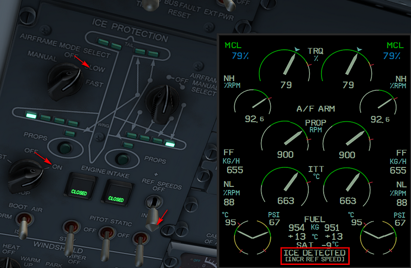
Climb: When passing FL100, turn off the landing lights and the
seat
belts sign. Set altimeters to 1013/29.91. Switch off aux fuel pumps,
STBY HYD, PTU and the autofeather. If you encounter icing conditions,
the "ICE DETECTED" message will show up on engine display. Switch on
anti-ice
system (AIRFRAME MODE SELECT - SLOW), props anti-ice (PROPS - ON) and
increase reference speeds by turning on the REF SPEEDS switch to ON.
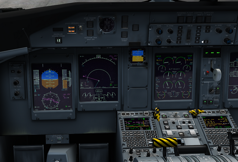
On reaching cruise altitude, set CL to 850 and reduce thrust to maintain 234kts (high speed cruise). At this point you can program the VNAV.
 |
Press VNAV button on the FMS, press LSK3 to select the waypoint you want to descend to (HABBS). For now, bypass each field by pressing ENTER until reaching the TGT V/S. When pressing enter on this field, the FMS will enter a cruise mode. |
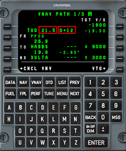 |
In this mode the FMS calculates
the top of descend (TOD) point. VNAV page shows the distance to the TOD
and estimated time to reach it. |
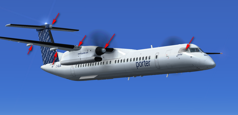
TOD is displayed on the flight path (small circle).
If you check visually the plane in flight, you can notice that
even
with anti-ice on, some parts are not de-iced, namely prop spinners and
the FO side window.
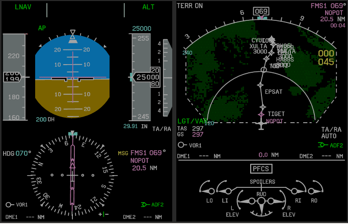
2 minutes before reaching the TOD, VNAV path symbol will
appear on the
PFD. Set the ALT SEL altitude to 3000ft, which is the published
altitude for our selected approach and click on VNAV button on the
autopilot panel.
Descend: After passing the TOD, reduce PL to maintain 240kts. Switch on passenger signs, set decision altitude (DA) (set 60ft in our case). passing FL100, set the destination airport pressure of 29.97 Inches, select seatbelts to ON and turn on Landing Lights. When passing the HABBS waypoint we will begin our approach preparations:
Arm the approach mode of the FMS by pressing "ARM APPROACH" and than "TUNE APPROACH" on the NAV page. This will also tune the correct ILS frequency at the NAV1 receiver. Bring up the NAV CDI pointer on the MFD by pressing the FORMAT button for >2 seconds, and set the ILS course of 58 degrees. We are now ready for the approach
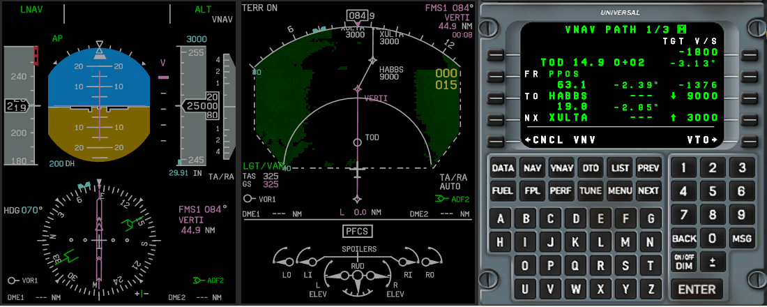
Shortly after passing HABBS the FMS will enter the approach mode, and the VNAV will also switch to approach mode, thus showing the simulated glideslope, and disconnect automatically cause we are below the glide slope altitude. It is theoretically possible to select ALT, re-engage the VNAV and fly a fully automatic FMS ILS approach, however for the purpose of this tutorial we will use the regular ILS approach in order to demonstrate the related autopilot functionality.
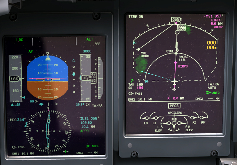
Upon the VNAV disconnect, set VS and ALT SEL to maintain the current vertical speed following by leveling off at 3000ft, the HDG bug to the current heading, press "HDG" to engage the "HDG SEL" mode, and . Switch NAV SOURCE to NAV1, and press APPR to intercept the ILS. Watch out IAS. Using PL, reduce the speed to under 200kts and deploy flaps to 5 deg. Switch on landing lights. Continue reducing speed, under 180kts set landing gear down and flaps to 10 deg. Approaching 1000ft, turn the bleeds OFF/MIN, advance the Condition Levers to MAX and disengage the autopilot by pressing the AP button on the glareshield or the red button on the yoke.
Landing: Deploy flaps to 15 deg. and maintain the speed of 130
kts. Maintain the approach power setting all the way until the main
wheels touchdown, after which reduce to FLT IDLE (a "click" will be
heard when just passing the FLT IDLE gate), settle the Nose Gear on
ground and reduce further to DISC. After touchdown, retract the flaps
and set the control lock. It is not necessary to use reverse thrust on
a long runway like CYUL 6L. Taxiing to the gate: a/col lights red,
switch off landing lights, switch on taxi light. Switch the wx radar to
standby, spoilers to "taxi", switch off auxiliary fuel pumps. Once at
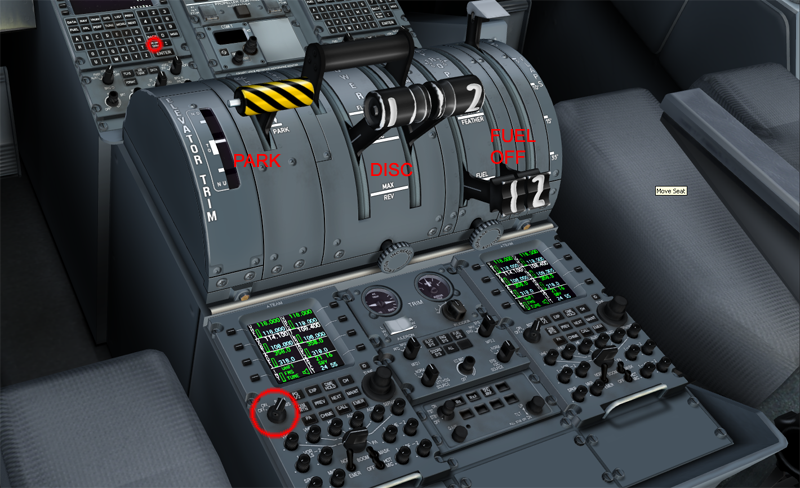
the gate, set parking brakes, move CL to START&FEATHER , PL to
DISC
and turn the Standby Hydraulic Pump and the PTU off. After 30 sec move
CL to FUEL OFF to shut down the engines.