UDP interface question for PRO version

Hi,
The recent patch for the Q400 included the UDP interface for cockpit interfacing. After successful installation of the patch I tried to implement a simple UDP test as I want to replace the XML interface by the UDP interface for my cockpit hardware.
First I configured the INI file correctly. Then I checked, that the port for listening to UDP datagrams gets active via netstat. The port is shown in the list, when P3D is started and the Q400 is loaded.
Then I used an UDP test utility to send my first datagram. I simply want to turn on the master battery switch. According to the documentation I sent the following UDP datagram:
65 F2 FF FF 10 03 00 01 01
The first two bytes are the WORD for 26098 (=header for Q400) in hex
The next two bytes are the WORD for the filter (FFFF = all data)
Then 1003 as the index of the master battery switch according to the variables list
Then 0001 as the length of the data (actually one BYTE)
And finally 01 to turn the switch on.
But unfortunately nothing happened. Therefor I tested with an UDP receiver listening to the configured port instead of the Q400 and I received exactly the message I composed. And it works locally sent on the same PC as well as sent from another PC in my network. I always received the correct datagram. So firewall is also configured correctly.
So I must do something wrong with my message. But I have no idea what. I run the 64-bit version of the Q400 under P3D 4.5 latest version.
Maybe someone of you have a hint for me.
Rgds
Reinhard
Comments
Hi,
By sniffing the traffic between the Remote FMS (great feature btw) and the Q400 I found the solution by myself.
First of all: The documentation for the UDP interface is wrong in one point: The header for the UDP packets in the PRO version is: HEX 21 52 !
My mistake has been, that I have to send WORD values in low/high byte order. So the correct datagram for turning the Battery Master to ON is:
21 52 FF FF 03 10 01 00 01
Rgds
Reinhard
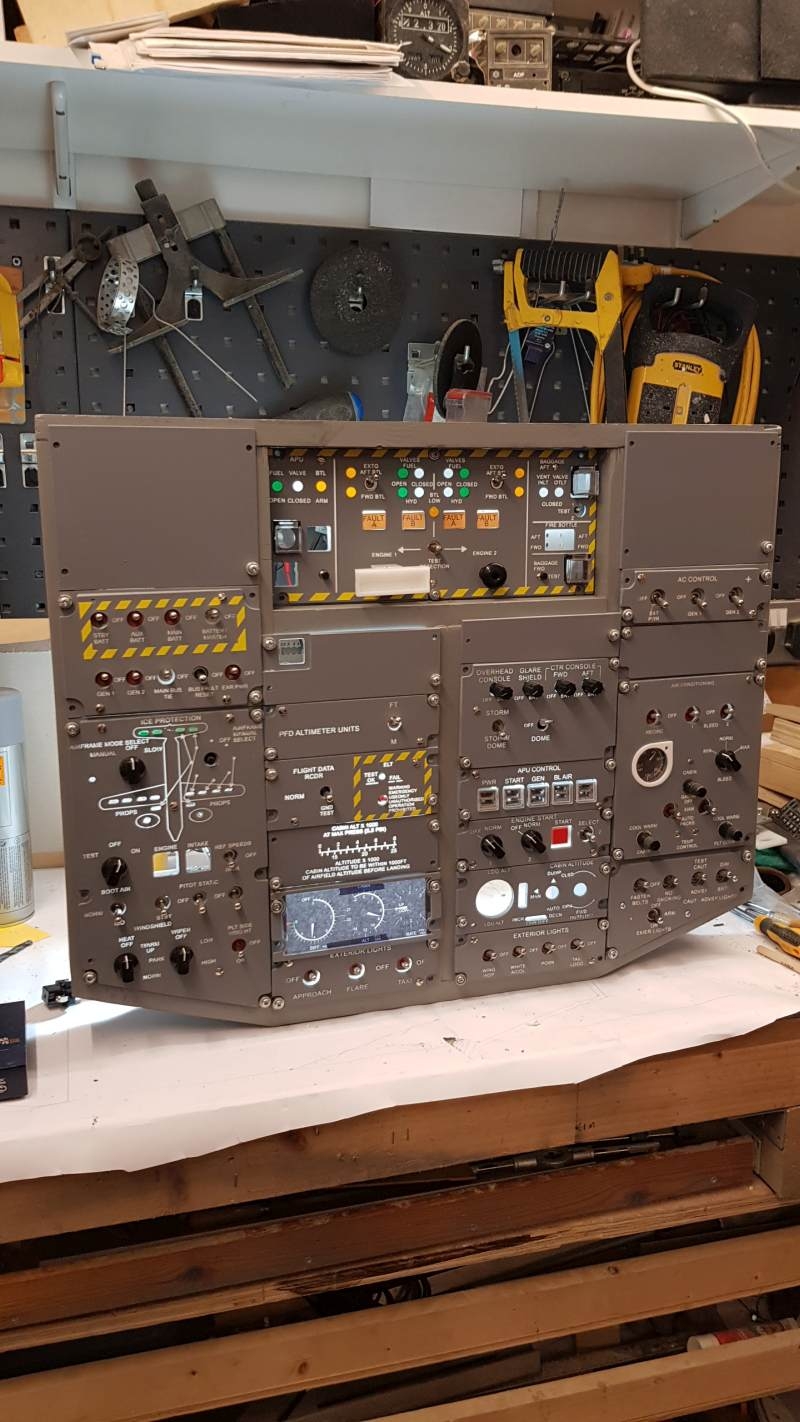
I make real nice laser cut panels.
I can only program them via the joystick connector or assigning a keystroke to them.
So I am very limited to what I can automate in my sim.
I will make custom panels for anyone that can help me.
I am already making them for my new sim so I can make more like mine or you can tell me what you need and I can make that. (as long as it a reasonable modification)
It has taken quite some time, money, and energy to become good at making realistic panels. I am sure someone out there has spent lots of time learning how to code and interface with flight simulators (I use P3D v4.5). Let's trade skills.
(I tried to post a picture of the kind of panels I make but the uploads kept failing)
Hi Reinhard.
Quite interesting your findings! I've managed to reproduced your test at my setup. As for input interfacing I feel that the XML interface is sufficient enough, I'm more interrested in reading output values (enginge data for gauges, notification/AP led, etc.). So I´m trying to sniff the relwant udp packets, but I haveing som problems break down the headers.
Could you please explain to me what you meen by: "My mistake has been, that I have to send WORD values in low/high byte order."
I do not understand how it 65 F2 FF FF 10 03 00 01 01 went to 21 52 FF FF 03 10 01 00 01
Hi,
A WORD is a two byte (16 bit) value. The index value for the Master Battery switch for example is hex 1003 as per documentation. But sending this command requires you to send first the low byte and then the high byte: So you send 03 first and the 10 (and not 10 and 03 as we might assume). This is called little-endian as far as I know.
Same with the word for the number of bytes of data: If you want to send hex 0001 you send first 01 and the 00.
Hope this explains it better. For receiving: I am also especially interested in the reading of datagrams. I was able to produce a broadcast stream in my network and reading all the traffic that the Q400 produces permanently. But that's a lot of traffic. Not sure how to handle this.
One thing described in the documentation did not work for me: In the documentation it's described, that you can configure several UDP connectors (from UDP 3 to 9). But I was only able to send/receive on number 3. Maybe this is an feature only available in the upcoming training version.
Rgds
Reinhard
Hi Reinhard and thanks for the info! I think I kind of understands it!
I've done some playing with Wireshark to figure if I can make some sense out of all the packages being sent from the Q400.
I did manage to set up a filter to listen for one specific var (electricsData_->control.instlight_ovhd - Index 100c) - Wireshark filter. udp contains 2152:ffff:0c10
But for now I have only managed to filter for vars that are in word, not vars that are in byte, float etc.
Not sure what I'm going to do once I figure it out. I do not see my self building a software myself to handle display all these values in my cockpit. Im using AirManager to do all the outputs, so for me I would like to see more Q400 vars available as L:Var´s.
One thing that have crossed my mind is to use the RPC interface, and create a gauge that will pass Q400 vars to some L:vars, that way I can subscribe to them in Air Manager. But then I would need to learn C++...
Has anyone gotten all the OUT to work? I am having issues with that..
Hi Reinhard
I have started looking at how to interface the via UDP following your logic open ports, check with netstat etc. I see the ini file contains an entry for UDP conector 3 (3RD party) that is enabled, can you tell me what else needs to be configured in this file ?
Thanks
Douglas
I am away from my sim for two weeks. So please standby for an answer.
Rgds
Reinhard
Thanks, I will keep working at it
Hi") ) The aircraft looks fantastic and I am looking forward to learning to fly it. I have been reading the forum for some time now so I am aware of the regular posts, gear pins and installs exhausted etc, so I know what to do about them. I have started my cockpit build with the overhead so I am very interested in how the interface works. The spread sheet in the docs looks great in the amount of possibility’s available.
) The aircraft looks fantastic and I am looking forward to learning to fly it. I have been reading the forum for some time now so I am aware of the regular posts, gear pins and installs exhausted etc, so I know what to do about them. I have started my cockpit build with the overhead so I am very interested in how the interface works. The spread sheet in the docs looks great in the amount of possibility’s available.
I have finally bought the Q400 Pro edition for P3d V5 while waiting on the Training / Cockpit edition ( no I am not asking when
I am able to build hardware and used SIOC for my last sim, but coding is not my area of expertise so please bear with me on basic errors and lack of programming understanding and hopefully my mistakes will help others.
Following Reinhards logic, I tested how to send UDP across my home network and found I could send and receive form all my computers and touch pads except the flight sim box , dedicated computer, clean install of windows 10 pro 2004update, P3d V5 and the FMC server ( also wire shark). After much investigation I found it was a network setting that was stopping it. It needs to be set to public not private which seems strange as this hides it from other computers.
Port rules were added to the fire wall for 49250 and 49260 and checking with netstat –a found to be on the list
I added the section to the ini file from the documentation UDP connector 4 then sent the packet for the battery master switch using Packet sender as per Reinhards format. At first there was no response and on further testing I found that I was entering the packet in the ASCII box rather than HEX, as soon as I sent HEX it works !.
I now put together a simple sketch for ardunio mega, which I am hoping to use as an interface, to send the packet via UDP, unfortunately this did not work. Using wire shark I can see the packet from both the ardunio and packet sender , from packet sender it arrives as 21 52 ffff 03 10 0100 01 But from the ardunio as 32 31 20 35 32 20 66 66 20 66 66 20 30 33 20 31 30 20 30 31 20 30 30 20 30 31 even though its sent as 21 52 ffff 03 10 0100 01.
Could anybody advise me on what to send from the ardunio or give me any other ideas on what to use ?
Thanks
Douglas
Hi,
Arduino obviously send the ASCII hex values for the single digits:
So you are sending the datagram (21 52 ...) but Arduino converts each digit into the ASCII hex representation.
Rgds
Reinhard
Thanks for the reply, i will do some more searching on the ardunio forum. its a shame that programs like simvim and mobiflight dont mention the Q400 even though they work with Xplane via UDP
Ok I have done some more testing and despite my lack of coding experience or any real knowledge, I have managed to get it to work. To send the datagram via an ardunio I used a HEX array which I declared first and then coded to send on the switch closing or send with the last byte set to 0 if you set the switch to off.
byte BattMasterOn[10] = {0x21, 0x52, 0xff, 0xff, 0x03, 0x10, 0x01, 0x00, 0x01};
I am sure there are experts that can explain it better.
Next challenge is to get the outs to work for LEDs any help with that would be appreciated.
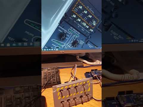
This is how it looks with my hardware
https://youtube.com/watch?v=Nwxp8_t2wMM
Ok I have done some more testing and despite my lack of coding experience or any real knowledge, I have managed to get it to work. To send the datagram via an ardunio I used a HEX array which I declared first and then coded to send on the switch closing or send with the last byte set to 0 if you set the switch to off.
byte BattMasterOn[10] = {0x21, 0x52, 0xff, 0xff, 0x03, 0x10, 0x01, 0x00, 0x01};
I am sure there are experts that can explain it better.
Next challenge is to get outs to work for LEDs any help with that would be appreciated.
This is how it looks with my hardware
Hi again
looking at outputs and again following Reinhards logic of testing the basics first, I have configured the fire wall with a rule for port 49250 outbound and tested between the sim computer and another with a basic UDP send and receiver, all good.
In the ini file where I added the UDP connector below. I have tried changing the UDP_BROADCAST_MASK= to 192.168.0.xx:49250 , the remote computer ip I also tried 255.255.255.0 broadcast to the network but I cannot see the UDP outputs on wireshark on the remote computer. If I run wireshark in loopback on the flightsim pc I can see the outputs. Do I need to configure this another way or am I completely in the wrong direction. Any help would be greatly appreciated
Again I am not a coder, just learning so please excuse basic errors.
[UDP_CONNECTOR_4]
UDP_ENABLED=1
SEND_RATE_DIVIDER=8; // 16 times per second
UDP_BROADCAST_ALLOWED=1
UDP_BROADCAST_MASK=127.0.0.1:49250
UDP_RECEIVE_ALLOWED=1
UDP_RECEIVE_MASK=0.0.0.0:49260
ICP_TX_FILTER=6152
ICP_RX_FILTER=6152
Hi,
As I have written above, I was only able to use UDP connector 3 for sending/receiving.
4 to 9 should work (but maybe with the training version only):
If you use UDP connector 4 as shown above, this could be one reason.
Rgds
Reinhard
Hi Reinhard
Thanks for the reply, this was indeed the problem, I remembered you said that and tried it last night. I now have the data on the network and have managed to set it uo to display on the serial monitor on the ardunio, I just need to figure out how to filter it for the index data and turn the leds on and off.
I have most of the overhead built but did not want to commit to building any more until I can interface it. Hopefully the Training / cockpit edition will be out soon and make this easier.
Kind Regards
Douglas
Hi,
Fine to hear. You are doing a great job. Thanks for sharing the pics.
Rgds
Reinhard
Hello there! Does this work only with P3D v4 or v5? I have version 1.020a installed on P3D v2.5 and I cannot get UDP ports active for connector 3.
I used netstat to check and I can see the the port for connector 2 (49240), I don't see the one for connector 3 (49260)...
My bad... It works if I install the 1.020b patch! I didn't know this specific version was needed, then I found a post about it.
Great work.
JP